Defects in Composite Materials: Detection and Analysis Using Ultrasound
The study of defects in composite materials using non-destructive techniques has gained significant importance in modern industry due to their widespread use in numerous industrial applications such as aerospace, automotive and construction, where their high performance and low weight are crucial.
The presence of defects in composite materials leads to a reduction in mechanical properties and, in certain cases, can affect aesthetic appearance. These defects may include cracks, delaminations, air inclusions, lack of consolidation, and variations in composition.
Non-destructive testing techniques—including ultrasound, thermography, radiography, visual inspection and electromagnetic methods—enable the detection and characterisation of defects without compromising the integrity of the material. This field of study is essential to ensure the safety, reliability and efficiency of components manufactured from composite materials, and its continued advancement contributes significantly to development and innovation across various industries.
Composite Manufacturing Processes
Focusing on defects caused by air inclusion in materials, the level of porosity primarily depends on various rheological and thermodynamic phenomena occurring during the manufacturing process. Two main groups of composite manufacturing processes can be identified, each affecting the porosity level of the final product differently:
-
Liquid Composite Moulding (LCM): This process is based on injecting resin into closed preforms containing pre-shaped fibres. Examples include RTM (Resin Transfer Moulding), where resin is injected at high pressure into a closed mould containing the fibres, and VARTM (Vacuum Assisted Resin Transfer Moulding), which differs from RTM by replacing the top part of the mould with a vacuum bag.
-
Pre-impregnated composites or prepregs: These consist of reinforcements, such as carbon or glass fibres, arranged in thin layers (typically unidirectional or woven) pre-impregnated with resin (thermoplastic or thermoset). The laminate is then formed by stacking layers (lay-up) and curing to create the final product.
Porosity Types Based on Manufacturing Process
-
Porosity in LCM processes: Mainly caused by air trapped during resin injection. This is due to the non-uniformity of the reinforcement, both in-plane and through-thickness, affecting the resin’s impregnating ability and resulting in uneven permeability. Additionally, chemical reactions during resin curing may generate volatiles that form porosity, or dissolved gases (e.g. moisture) may nucleate under curing temperature and pressure conditions.
Three types of pores can be distinguished by location (they may also be categorised by size: micro: µm scale, meso: µm–mm, and macro: mm):
-
Intra-bundle: pores between fibres within the same tow.
-
Inter-bundle: pores between tows. These are larger than intra-bundle pores transversely, but smaller longitudinally.
-
Dry spots: large pores in preform areas caused by poor resin distribution, visible to the naked eye.
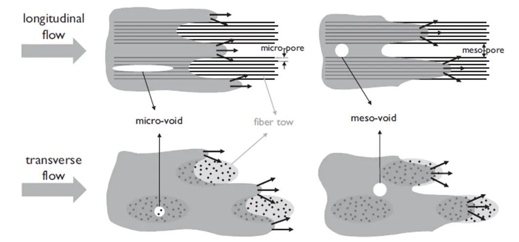
Figure 1. Examples of pores produced during LCM manufacturing processes according to size.
-
Porosity in prepreg composites: Unlike LCM processes, porosity in prepregs typically originates during pre-impregnation of fibres, layer stacking (laying-up), and subsequent curing stages. The main types of porosity are:
-
-
Intra-ply: pores between fibres within a single laminate layer, caused by incomplete impregnation during prepreg production. Also known as dry areas, they typically appear as channels running along fibre tows. These may disappear once resin flows through them under pressure and temperature.
-
Inter-ply: pores between laminate layers, mainly due to air entrapment during lay-up.
-
Resin porosity: may occur due to volatile generation during curing or dissolved moisture. Therefore, lay-up and curing are critical to minimise porosity in such composites.
-
-
-
Two main curing processes exist:
-
Autoclave curing: Produces high-performance composites using high pressures (7–8 bar), facilitating pore extraction and achieving high fibre volume fractions. Drawbacks include high cost and the need for optimal curing cycles.
-
Out of Autoclave (OoA): Uses only vacuum pressure (1 bar) to compact laminate layers (VBO – Vacuum Bag Only) and extract porosity. It significantly reduces cost and enables larger part production. However, lower consolidation pressures result in higher porosity and lower surface quality compared to autoclave-cured parts.
-
Automated Tape Laying Processes
During laminate lay-up to create a preform, automated prepreg laying using tapes (ATL – Automated Tape Laying and AFP – Automated Fibre Placement) is a prominent process. In thermoplastic matrices, in-situ consolidation occurs as layers are laid. For thermoset matrices, post-curing is required due to slower consolidation speeds.
Defects during automatic tape laying may include:
-
Gaps: voids between successive tapes due to lay-up inaccuracies.
-
Overlaps: opposite of gaps, where tapes overlap.
-
Wrinkles, bridging defects and twisted tows.
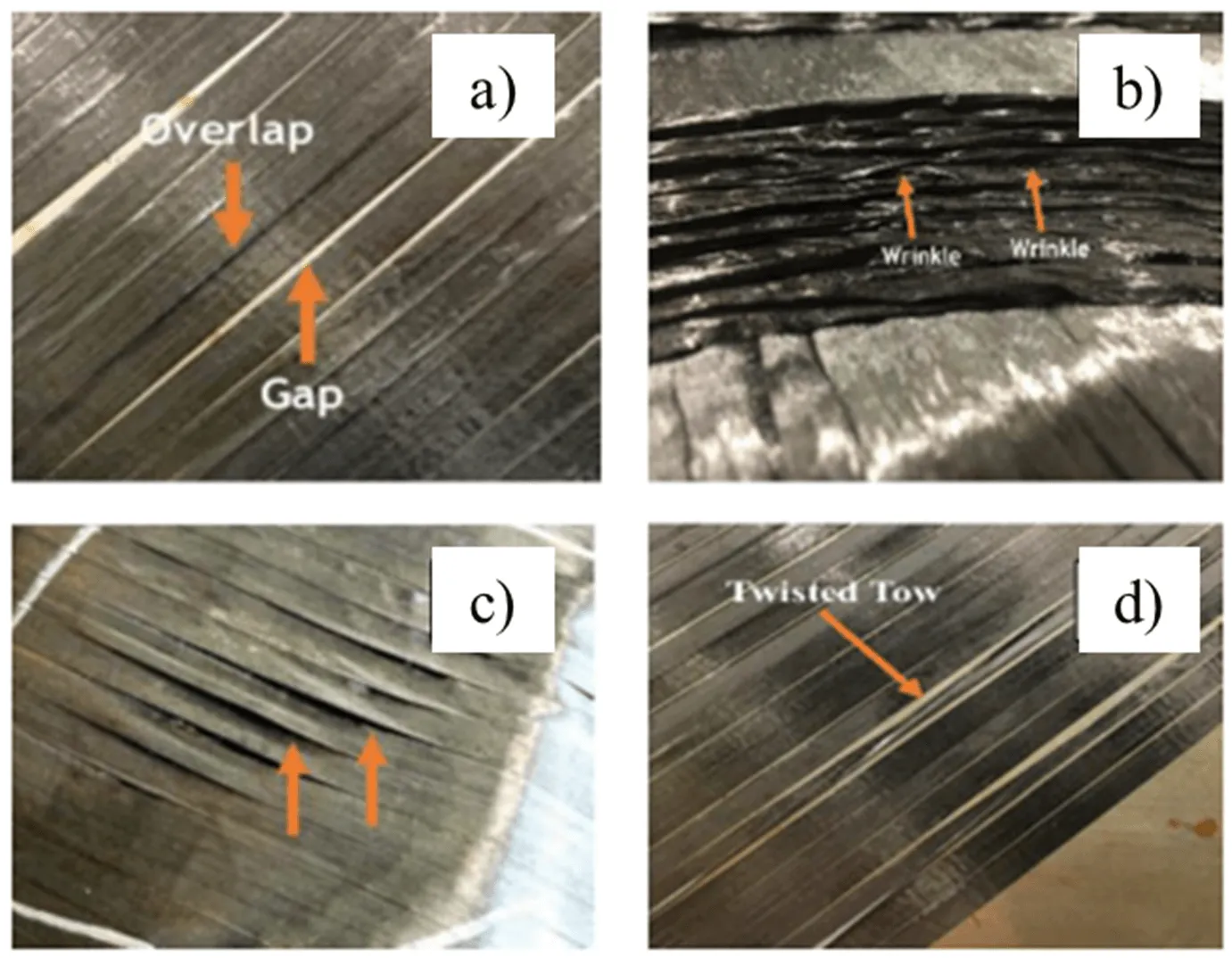
Figure 2. Typical defects in automatic tape laying processes.
Characterising Porosity with Ultrasound
Various non-destructive techniques are available to assess porosity level, size and defect location in composites, including thermography and X-rays. Among them, ultrasound is one of the most widely used and is based on the propagation of sound waves through the material.
When an ultrasound source is applied to a material’s surface, it emits high-frequency pulses that travel through it. If the material is defect-free, the waves propagate uniformly and reflect at interfaces or internal defects. If a defect is present (e.g. a crack or delamination), some wave energy is reflected or scattered instead of continuing.
By measuring and analysing the reflected ultrasonic signals, the presence, location, size, and nature of internal defects can be determined. A key drawback is the need for a coupling agent between the transducer and the material to prevent an air gap, which reflects the entire signal. The technique is also relatively slow and less flexible for large or non-flat surfaces.
Ultrasonic Inspection Methods
Different inspection methods exist depending on the transducers used [3]:
-
Pulse-echo: the simplest method, using a single transducer to emit and receive signals.
-
Pitch & catch: uses two transducers, one emitter and one receiver.
-
Phased array: emits multiple rectified pulses with time delay control, improving resolution and enabling application to curved surfaces and narrow components. Widely used in aerospace.
-
Laser-based methods: operate on different physical principles from ultrasound.
To avoid coupling agents, other techniques include:
-
Immersion: the sample is submerged in water (which may affect material properties).
-
Air-coupled: contactless inspection, faster and low-cost but with reduced sensitivity and precision.
Ultrasound can also be applied at an oblique angle to detect perpendicular or weld-related defects—this is known as oblique incidence ultrasound.
Result Representation
Depending on the inspection type, results may include:
-
A-scan (Amplitude-scan): real-time surface scan using pulse-echo, showing reflections (signal amplitude vs time) from parallel defects like delaminations, flat pores and erosion.
-
B-scan (Linear-scan): 2D sectional view showing signal arrival time vs transducer position. Detects fibre-related defects (e.g. wrinkles).
-
C-scan (Through Transmission): high-resolution mapping of defect size, position, and shape using opposing transducer and receiver. Requires data acquisition systems.
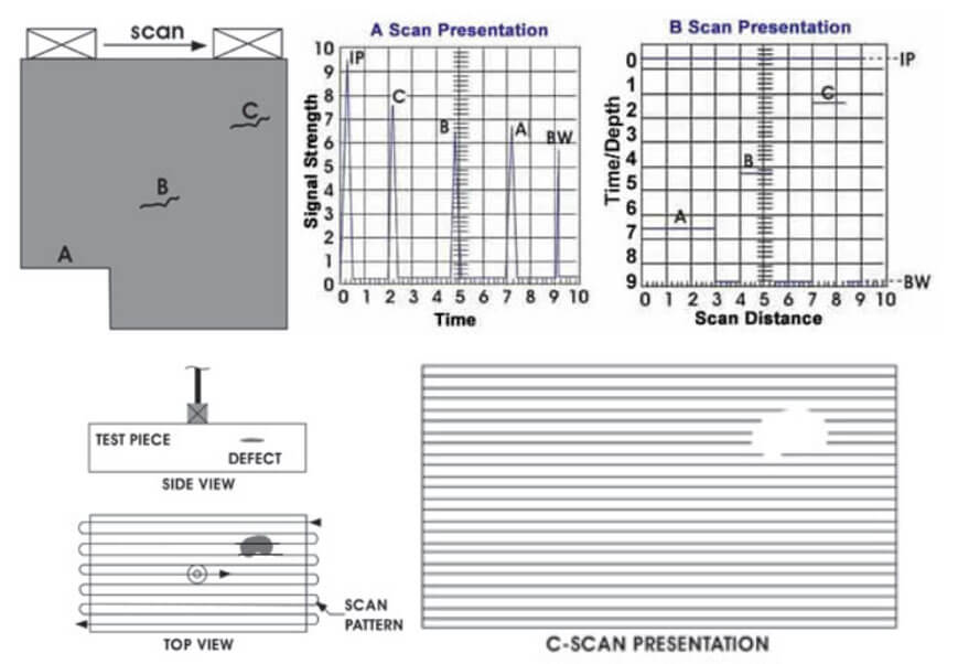
Figure 3. Example of different result representations depending on scan type (IP: Initial Pulse, BW: Back Wall pulse).
Composite analysis is complex due to variable material composition, leading to continuous wave reflection and scattering as they pass through fibres and matrix. Sound velocity also varies across the material thickness, causing high signal attenuation. Defining suitable transducer characteristics (e.g. gain, frequency) is essential, especially for conventional pulse-echo. In composites, phased array or more advanced techniques like X-ray with Micro CT are recommended, providing 3D imaging based on absorption and scattering differences. However, these are expensive and heavily dependent on image processing.
How Can AIMPLAS Help You?
AIMPLAS has ultrasound equipment capable of performing pulse-echo and pitch & catch techniques (5 and 10 MHz transducers).
Figure 4 shows the thickness measurement of a 10-ply woven carbon fibre (0/90°) prepreg laminate with epoxy, manufactured at AIMPLAS via OoA. Laminates were also produced with ad hoc defects simulating AFP deposition faults, detectable by the equipment.
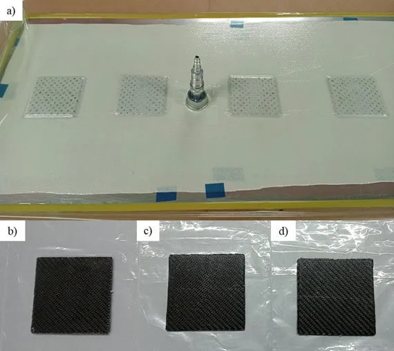
Figure 6 shows A-scan reflections for two manufactured defects (both 1.8 mm from the surface, with dimensions 1.8 × 5 mm and 1.8 × 1.5 mm). In both cases, reflections at ~2 mm indicate defect start, and at ~4.5 mm indicate the laminate bottom. In the larger defect, the reflection is earlier due to lower thickness—layers collapsed into the gap during vacuum application. Notably, greater defect size leads to lower final reflection amplitude due to energy absorption.

Figure 5. Thickness measurement in reference sample (5 MHz): (1) Transducer dead zone, (2) Reflections from porosity in successive laminate layers (inter-ply gaps), (3) Reflection from laminate bottom.
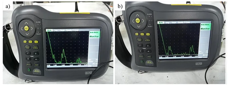
Figure 6. Reflection spectra (A-scan, 5 MHz): (a) 5 mm defect, (b) 1.5 mm defect.
Conclusion
The study of defectology in composites is of great industrial and research interest, as defects significantly affect the final properties, reliability and safety of manufactured components. It is therefore crucial to use techniques that can assess these defects, with non-destructive methods being highly advantageous due to their non-invasive nature. Among them, ultrasound stands out for its simplicity and wide applicability, depending on the materials being analysed.
References
M. Mehdikhani, L. Gorbatikh, S. Lomov y I. Verpoest, «Voids in fiber-reinforced polymer composites: A review on their formation, characteritics, and effects on mechanical performance,» Journal of Composite Materials, 2018.
D. Sáenz, «Characterization and real-time process monitoring of thermoplastic composites manufacturing processes,» Polytechnic University of Madrid, 2020.
J. Jodhani, A. Handa, A. Gautam, Ashwni y R. Rana, «Ultrasonic non-destructive evaluation of composites: A review,» Materials Today, 2023.
«Nondestructive Evaluation Techniques: Ultrasonic Testing,» Iowa State University, [En línea]. Available: https://www.nde-ed.org/NDETechniques/Ultrasonics/index.xhtml.
H. Taheri y A. Arabi, «Nondestructive Ultrasonic Inspection of Composite Materials: A Comparative Advantage of Phased Array Ultrasonic,» MDPI, 2019.
J. Kratz, P. Galvez, L. Rhian, J. Belnoue y K. Potter, «Lab-based in-situ micro-CT observation of gaps in prepreg laminates during consolidation and cure,» University of Bristol, 2021.